My idea of using a XV-11 Lidar as a cheap sensor option actually started from this video from Robotics Weekend.
While waiting to get more components to experiment the same setup as his, I utilize other resources that I have to get some output and verify that my lidar is working. I have a Raspberry Pi 3 and an Arduino Uno boards.
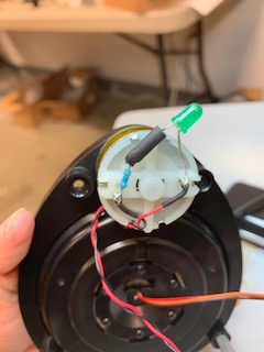
Open up the Lidar
I got the lidar on eBay for about $60 which is not too bad. The only info I know about this unit is its model XV-11. After reading from XV11 Hacking, I understand more that there are 2 versions of this type of lidar, the earlier version is powered by 3.3v and the later version is powered by 5v. The motor can be powered by 3.3v, RX and TX port are 8N1 3.3v at 115200 baud rate for all units.
So I opened up the cap of the unit (top 4 screws) to investigate the unit, and I have a 5V powered unit.

Testing the Lidar on Arduino Uno
Connecting
RED – 5v
BLACK – GND
BROWN(LDS_RX) – pin 4
ORANGE(LDS_TX) – pin 3
(PLEASE NOTE you want 3.3v for your TX and RX so that you would not damage your unit, I used a voltage divider setup to obtain this. Although before I know about this, I did connect the TX and RX directly to the Arduino pins. Someone warned me later but good thing my lidar was not damaged!)
Arduino codes:
#include

#define rxPin 3
#define txPin 4

SoftwareSerial mySerial(rxPin, txPin);
char pinState;

void setup(){
pinMode(rxPin, INPUT);
pinMode(txPin, OUTPUT);
Serial.begin(115200);
mySerial.begin(115200);
}

void loop() {
if (mySerial.available()){
pinState = mySerial.read();
// pinState = Serial.read();
// mySerial.print(someChar);
Serial.print(pinState);
}
}
After connecting the lidar to Arduino, Arduino to PC (through USB) and upload the code, I have the Serial Monitor screen on. Then, unplug 1 power wire connect to the unit and plug it back in again. Now, the unit shows to have some response because it should output something on the Serial Monitor. SoftwareSerial does not support up to 115200 baud rate, it does not yield anything readable. One of the explanation for this is because SoftwareSerial is typically not ideal for high speed serial reading. However, some response at least gives me hope that my lidar is working.
Test Lidar on Arduino Micro Pro [Update (09/16/2019)]
After more than a year later, I finally resume to this project and get the Lidar being controlled by Arduino. In order to get this project going successfully, you would need to use a board with at least 2 hard serial ports.
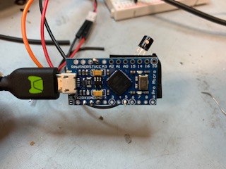
This time, I use a Arduino Micro Pro (just like the one Robotics Weekend used in his example).
This board has the flavor of Arduino Leonardo. It has a dedicated USB connectivity and a separate serial (RX, TX), which is what we need: 2 hard serial ports. This is different from Arduino UNO or Mini or Nano, these board share the USB and (RX, TX) pins which means if you use the USB to read serial in these boards, you cannot use TX & RX pins. It’s why I had to use SoftwareSerial in the test above.

What else you should need?
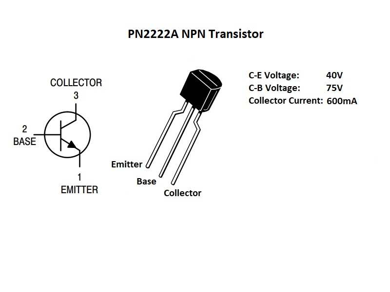
- 1 Mosfet (or 1 transistor)
- 1 Diode or LED & 330ohm resistor
- Some jumper wires
I got one of these Elegoo kits when I started doing electronics, it has most of the stuffs mentioned above (& more) except the Mosfet (but you maybe able to get away with the transistor like I do).

- Solder iron or you can use a board with headers on breadboard to try out.
Robotics Weekends did a very nice job to have a schematic on his tutorial video. Jump over at 0:32
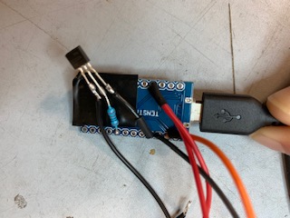
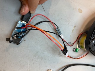
My wiring
The logic unit:
Arduino VCC < — > Red wire
Arduino Ground < — > Black wire
Arduino RX < — > Orange wire
The motor:
So the MOSFET IRF640N I have was no good for this application, somehow it did not yield enough current for the motor to spin. So I chose to use Transistor as alternative, and exactly this transistor coming with the Elegoo kit.
Arduino Ground < — > Transistor Collector
Arduino Pin 5 <– > 1K ohm resistor < — > Transistor Base
Arduino VCC <–> Red wire
Transistor Emitter < — > Black wire
Diode is supposed for protection that only allows current flow in one direction. Bad news is I don’t have any diode around. So I come up with alternative as using LED + a 330ohm resistor. LED’s nature is also only allowing current flowing one way, but that’s not an absolute guarantee but I take my chances!
The code
I’m just repeating what Robotics Weekend already mentioned for completeness. You can download the arduino code from getSurreal here and upload to the Arduino Micro. Uploading codes into this board could be another ordeal if one steps into the wrong foot into it. But that maybe another topic, I won’t go into detail here. If you run into problem, you can drop a comment and I may be able to share what I experienced.
If all the wiring is correct, and the codes are uploaded successfully, the unit should start spinning the moment you give it power.
The default RPM of the unit is 200 (also minimum limit, with 300 is the max). I’m using Linux, to change the RPM of the unit in Linux, I can type this in terminal, for example:
echo -e "SetRPM 200" > /dev/ttyACM0
You can go to Visual in ROS part if your unit is successfully running at this point.
Test Lidar on Raspberry Pi
From my experience, starting with the RPi is actually easier than with the Arduino board. If you have a Raspberry Pi board, it’s probably better to start from here, and not worry so much about all the electronic current, voltage. I found Tobias Weis instruction working out the best for me.
On the side note, you should also enable UART on your Rapsberry Pi so there is open communication on the Serial port (follow this instruction ). If using Raspberry Pi 3, your port can be different from the instruction, you can try port/dev/ttyS0 if dev/ttyAMC0 does not work. By running the Python script on Tobias website alone, I can see some data running on terminal.
(PLEASE NOTE: you do not have to make the motor running to test. However, I realized that if the motor does not spin, the lidar does not generate data. So you can use your finger and spin the top of the lidar yourself, you would see some data showing. I think as the data showing, it confirms that the lidar is working.)
Visualize through ROS
At this point, I successfully got the unit running by connect directly to the RPi. To visualize the laser data on ROS, I have ROS installed in both your PC and the RPi. Then follow the set up steps that the Robotics Weekend does in the first video to have your ROS-PC connect to ROS-RPI master.
To run the neato_laser_publisher node on my Rpi 3, I run this on the Pi’s terminal:
$rosrun xv_11_laser_driver neato_laser_publisher _port:=/dev/ttyS0 _firmware_version:=2
Then head over to local PC terminal, and run this command:
$rosrun rviz rviz -f my_frame
(my_frame here is neato_laser )
Credits:
Robotics Weekend:
http://roboticsweekends.blogspot.com/2017/12/how-to-connect-neato-xv-11-lidar-to.html
Xv11 Hacking:
https://web.archive.org/web/20150326122026/http://profmason.com/?p=13246
Control on Arduino:
Neato Robotics XV-21 Vacuum Cleaner: Cheapest Laser Scanner Ever!
Control on Raspberry Pi:
GetSurreal Firmware:
https://github.com/getSurreal/XV_Lidar_Controller
How to get fixed frame on Rviz:
https://answers.ros.org/question/232731/how-to-start-rviz-with-a-fixed-frame/
